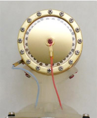
Condenser mics are a little more complicated - we'll try to provide a very simple explanation! The condenser employs a capsule (Fig. 1.2) consisting of a solid metallic disc called the backplate and, on one or both sides of the backplate, a very thin conductive plate called a membrane. The membrane, usually gold-sputtered Mylar, moves relative to the fixed backplate as it is displaced by incoming sound pressure. The plates form a condenser, or capacitor, and require an external dc voltage source for polarization, one plate being negatively-charged, the other positive. In its steady state, the mic's output is zero because the circuit is in a state of equilibrium. Motion between the plates caused by incoming sound pressure waves displacing the moveable plate results in rapid changes in capacitance proportional to the displacement of the plate. Thus, output voltage is the result of constantly-changing capacitance. The relatively low output of the capacitor means a separate amplifier stage inside the mic must be used to increase voltage output to a usable level. Most modern condensers employ either a solid-state or vacuum tube amplifier, while the most sought-after vintage mics utilize a vacuum tube design. Condensers tend to emphasize the high end of the audio frequency spectrum, and well-made ones are found in recording studios around the world. Though their design leads to some inherent shortcomings "high frequency peakiness," poor performance in high humidity and, in some cases, distortion artifacts that necessitate "fixing" the track at mixdown - they are an excellent choice for a wide range of applications and can make excellent companions to ribbons.
Fig. 1.2 - condenser mic capsule

